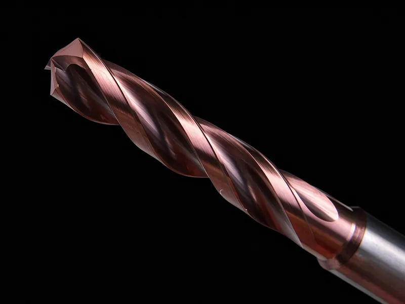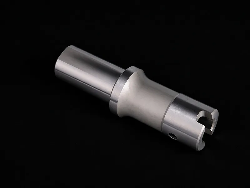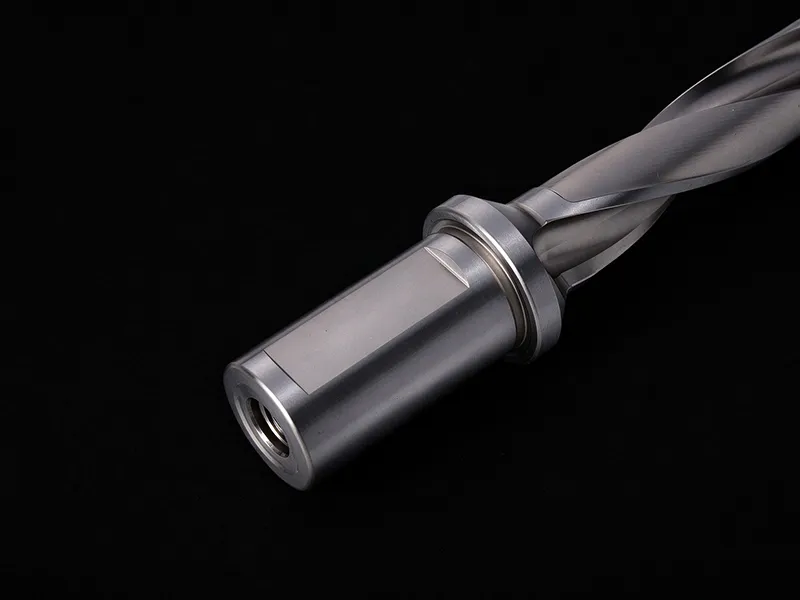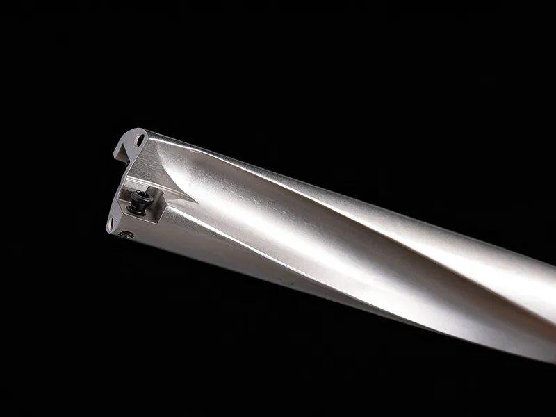
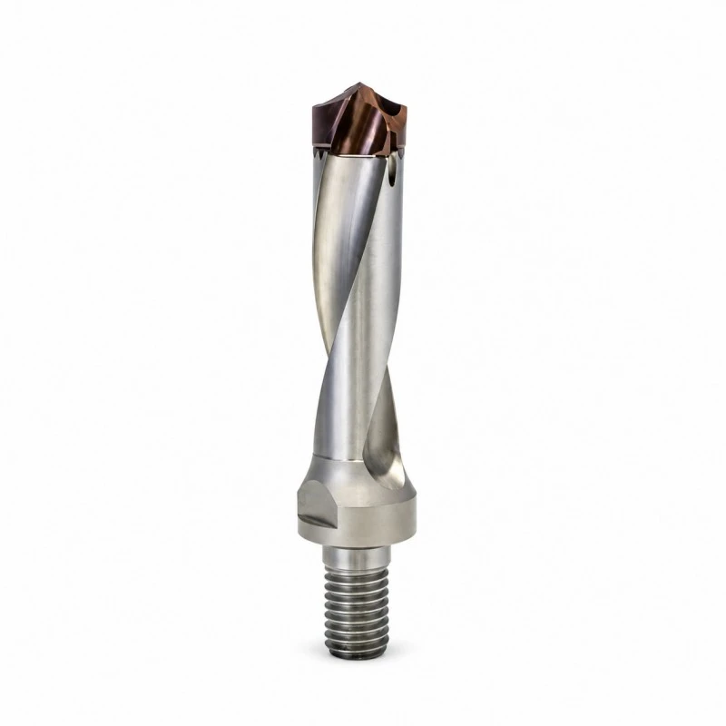
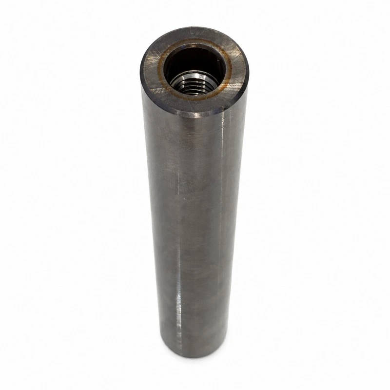
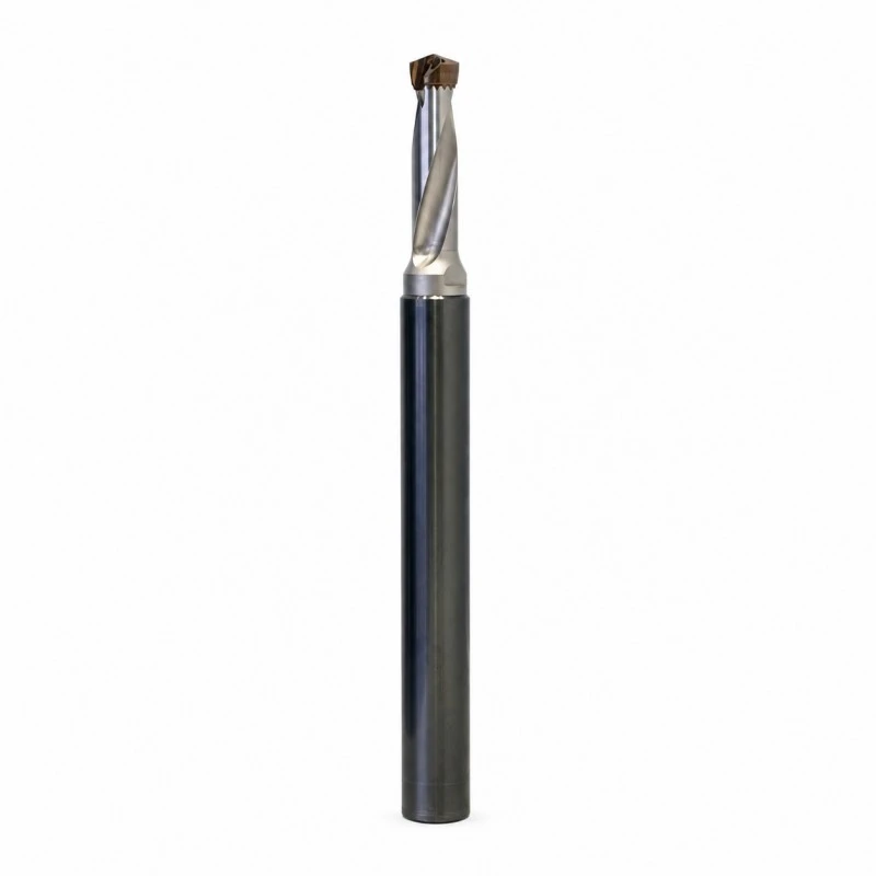
Internal Coolant Anti-Vibration Saber Tooth Boring Bar
For assemblies requiring coolant across the TF/KZ joint, RONGKE Internal Coolant Anti-Vibration Saber Tooth Boring Bar supports selection around the TF/KZ joint and its continuous coolant route. Contact us for wholesale enquiries. Select the TF cutting-diameter group and M10 or M12 support separately. Include the assembled connection details with your inquiry.
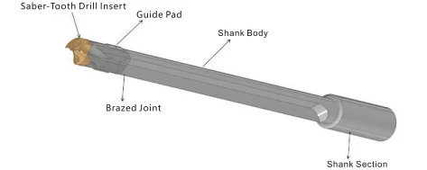
Source the Internal Coolant Anti-Vibration Saber Tooth Boring Bar from RONGKE, a manufacturer in China, with order details focused on the TF/KZ joint and its continuous coolant route. The internal-coolant anti-vibration saber-tooth assembly combines the front module and support shank with a coolant route to the cutting end. The connection must preserve both mechanical seating and coolant continuity through the assembled components.
Key Facts at a Glance
|
Item |
Details |
|
Product scope |
The TF/KZ joint and its continuous coolant route |
|
Primary distinction |
TF module selection defines cutting size, while the KZ M10/M12 group defines the support connection. |
|
Diameter / size reference |
Ø12–20.50 mm in the TF table |
|
Reach / configuration |
100 / 150 / 200 / 250 / 300 mm |
|
Ordering focus |
Verify the coolant path across the joint |
|
Assembly focus |
Match the mechanical module group |
|
Verification focus |
Tf-to-kz coolant continuity, joint leakage and cutting-end outlet condition |
|
Item |
Specification |
|
Front-module diameter |
Ø12–20.50 mm in the TF table |
|
Module series |
TF02 / TF03; the table does not expressly identify a 3.25D series |
|
TF03 example |
TF03-16.00-M12: D 15.51–16.50 mm; L 58; L1 76.5 mm |
|
Module joint |
M10 for D 12–15.50; M12 for D 15.51–20.50 mm |
|
KZ support lengths |
100 / 150 / 200 / 250 / 300 mm |
|
KZ support diameters |
M10 group: D 20, D1 10.5; M12 group: D 25, D1 12.5 mm |
|
Cutting component |
Saber-tooth tip matched to the selected TF module seat |
|
Coolant interface |
Joint and inlet drawing required; no universal pressure rating stated |
Component Roles
The TF module and KZ support meet at a threaded, seated joint. Assembly verification must include fluid transfer as well as the mechanical fit at that connection.
Where This Configuration Fits
Choose the Internal Coolant Anti-Vibration Saber Tooth Boring Bar when the job calls for the TF/KZ joint and its continuous coolant route. This selection concerns coolant transfer through a matched TF front module and KZ support. It suits an application requiring that internal route, subject to confirmation of the assembled connection and supply.
Selection guide — Coolant route vs support size: TF module selection defines cutting size, while the KZ M10/M12 group defines the support connection. Verify fluid continuity through the selected combination; the thread alone is insufficient.
Four Configuration Decisions
1. Verify the coolant path across the joint
Check that the selected front module and KZ support maintain a continuous fluid route. A correct thread pairing alone does not establish the assembled coolant connection.
2. Match the mechanical module group
Use the TF Ø12–20.50 mm table and its M10/M12 connections. Keep module diameter and support-shank diameter as separate selection dimensions.
3. Agree outlet and leakage checks
Request verification at the assembled module joint and cutting-end outlets. Test conditions must be agreed because the table gives no universal pressure-test specification.
4. Choose support length for the actual access
KZ tables list 100, 150, 200, 250 and 300 mm. Include front-module dimensions and holder engagement when reviewing the final projection.
Order Verification
Production & inspection
Use TF-to-KZ coolant continuity, joint leakage and cutting-end outlet condition. Agree coolant medium, assembly condition and acceptance criteria before a flow or leakage check; specify pressure and duration separately if a pressure test is requested as the inspection focus. Ask for the measurement method and acceptance limits to be stated in the quotation if a dimensional report is required.
Replacement Order Details
For the Internal Coolant Anti-Vibration Saber Tooth Boring Bar, send our factory the selected reference, quantity and requirements for the TF/KZ joint and its continuous coolant route. RONGKE can prepare the supplier quotation around that configuration.
FAQ
1. Q: Does matching M12 automatically confirm coolant continuity?
A: No. The joint must also preserve the actual coolant-transfer route and sealing arrangement.
2. Q: Is the KZ shank diameter the cutting diameter?
A: No. TF identifies the cutting-diameter group; KZ diameter describes the support shank.
3. Q: What coolant test can be specified without inventing a catalog rating?
A: Agree flow continuity and leakage checks, with any pressure, duration and limits explicitly specified.
4. Q: Is the KZ length the total assembled tool length?
A: No. Add the front module and account for holder engagement and other joint dimensions.
Related Category
Send Inquiry
Contact Info
-
Address
No. 399 Haohai Road, Binhai New Area, Economic Development Zone, Fenghua District, Ningbo City, Zhejiang Province, P.R.China
-
Tel
-
Email
Request a quotation from RONGKE for standard U drills, modular deep hole drills and customized CNC cutting tools. Share your machining requirements, tool dimensions and order quantity for professional product recommendations.
Related Products
News Recommendations